Complete setup guide for the intercom system, Amika tablets, SIP audio, resident badges, software updates, and relay box management.
Please keep these access credentials available during installation.
Installer access
Amika installer code: 571810
Intercom installer code: 571810
Intercom SIP account
SIP username: NewIntercomFeller
SIP password: 77392675
SIP domain: sit.eco-system.ch
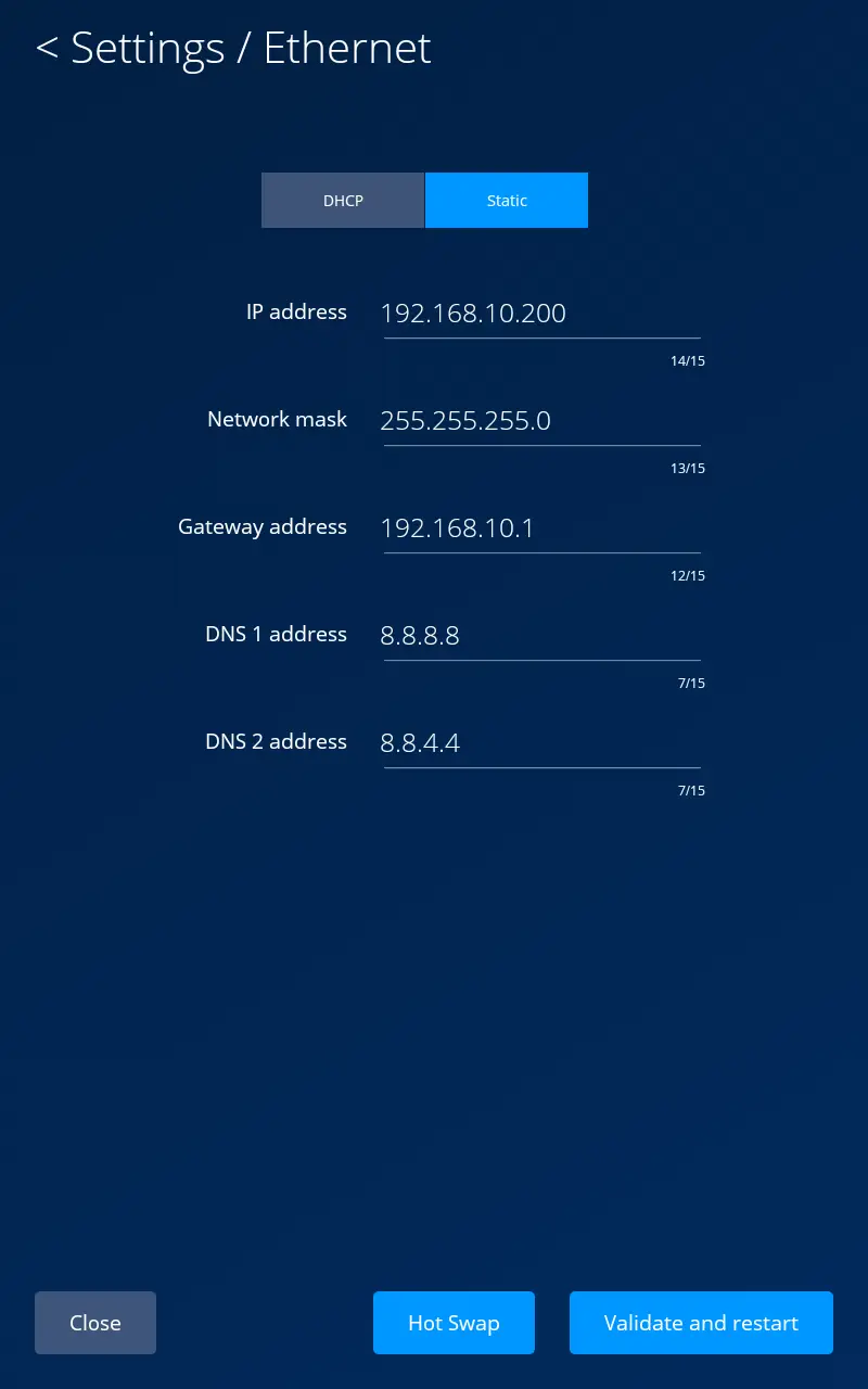
Open the intercom Ethernet settings and configure the network parameters so that the device is compatible with the local network.
The intercom IP address must be reachable from every Amika tablet that is to be paired with it.
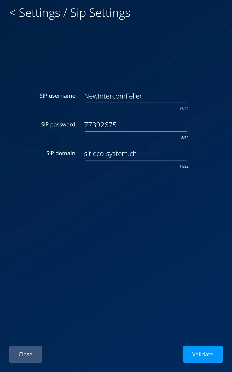
Open the intercom SIP settings and enter the following account details so that the intercom can register with the SIP server.
SIP username: NewIntercomFeller
SIP password: 77392675
SIP domain: sit.eco-system.ch
After entering the credentials, select “Verify”.
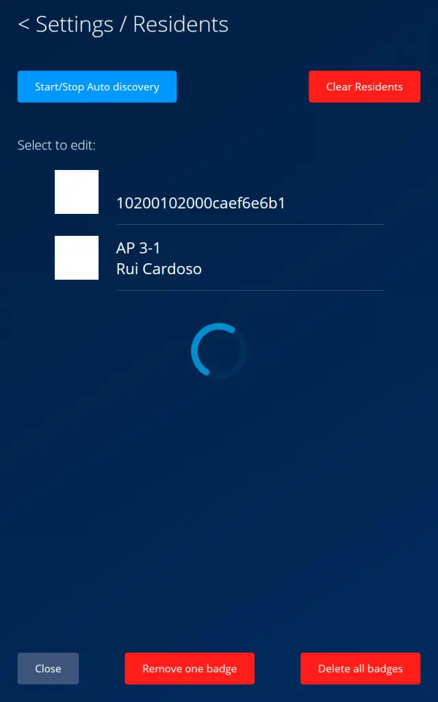
Use either automatic detection by the intercom or manual pairing via each individual Amika tablet.
Automatic detection by the intercom
Keep the detection page open until all expected Amika tablets appear in the resident list.
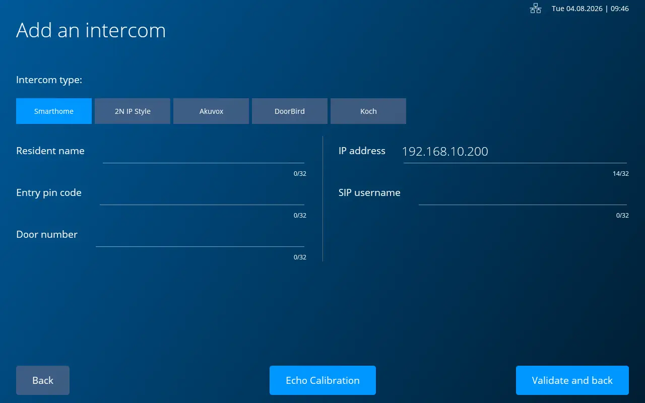
Network check: If the intercom IP address is not already filled in, the Amika device is not communicating with the intercom. Please check the network connection before continuing.
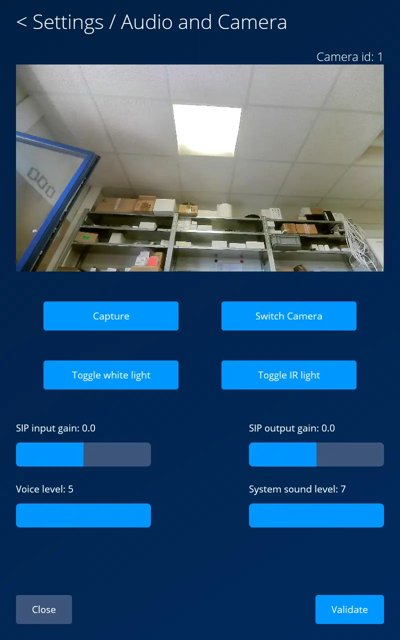
The default SIP audio levels are already calibrated. We recommend leaving these values unchanged.
Only change the SIP input or output gain if you want to resolve a confirmed issue with the audio levels.
Add or remove badges for a resident
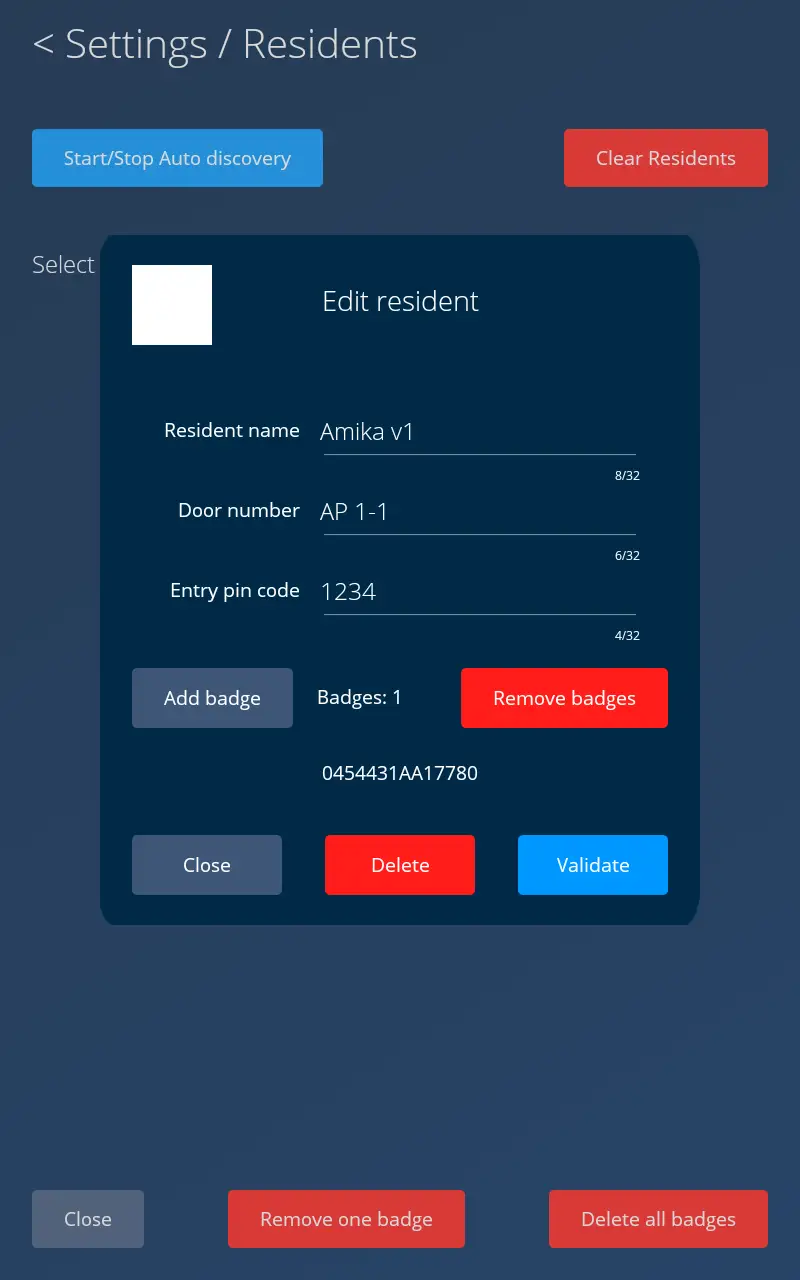
Open the resident management page, select “Add badge”, and hold the badge to the scanner. The number of badges increases and the badge ID is displayed on the screen.
To remove all badges assigned to this resident, select “Remove badges” on the same page.
Delete badges globally
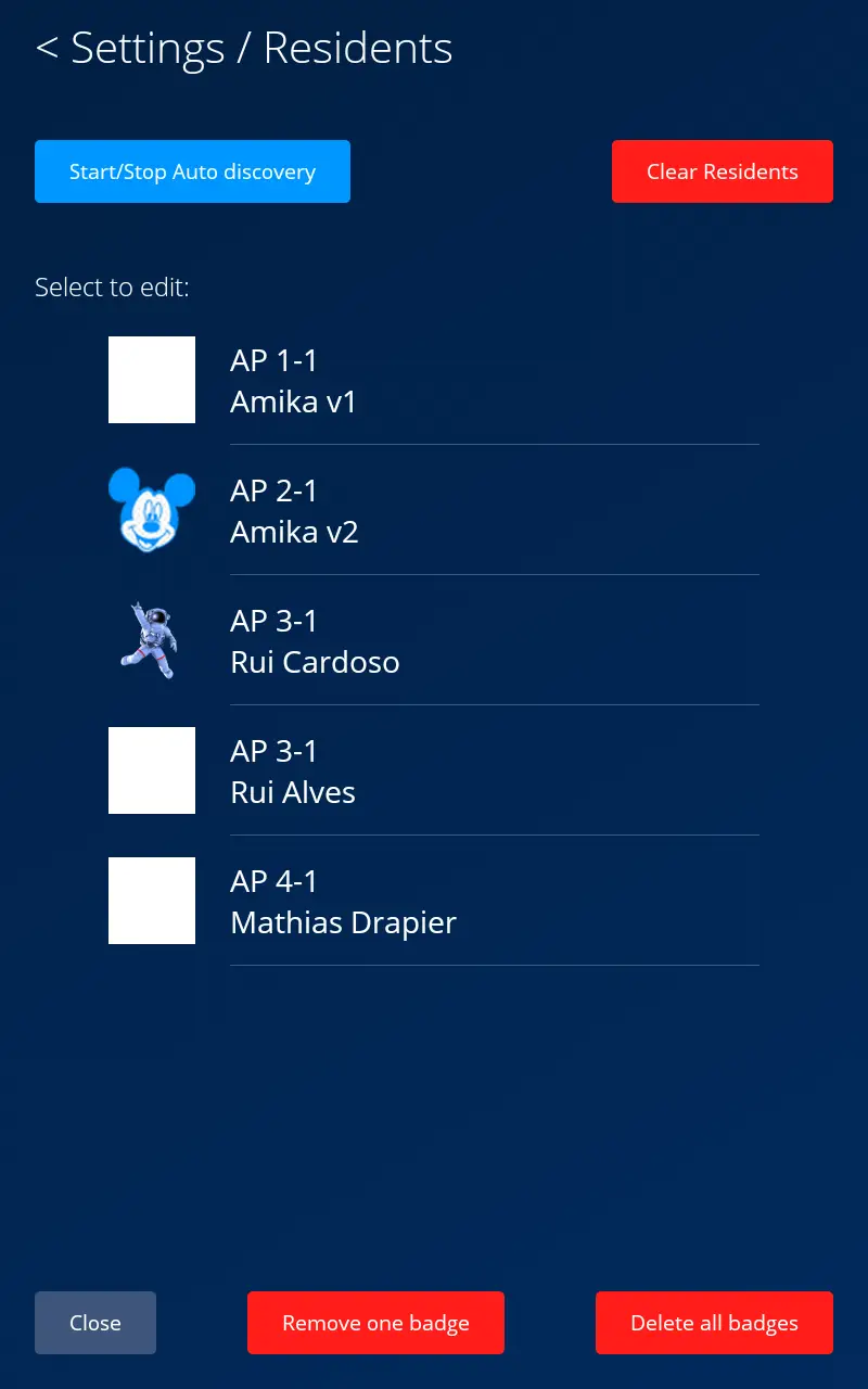
Under “Settings” / “Residents”, select “Delete a badge” and scan the badge within three seconds to delete it from the system.
Select “Delete all badges” to remove all badges registered in the system.
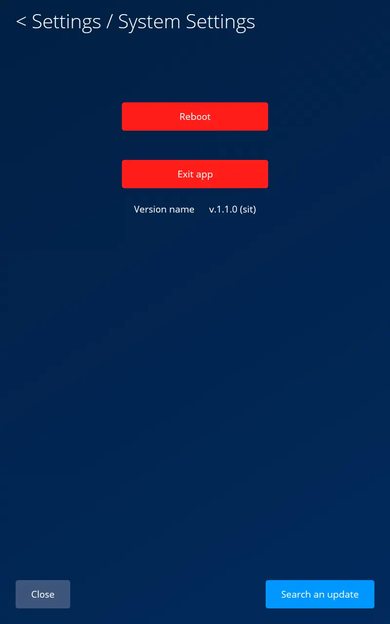
Open “Settings” / “System settings” and select “Check for updates” to prompt the intercom to search for an available software update.
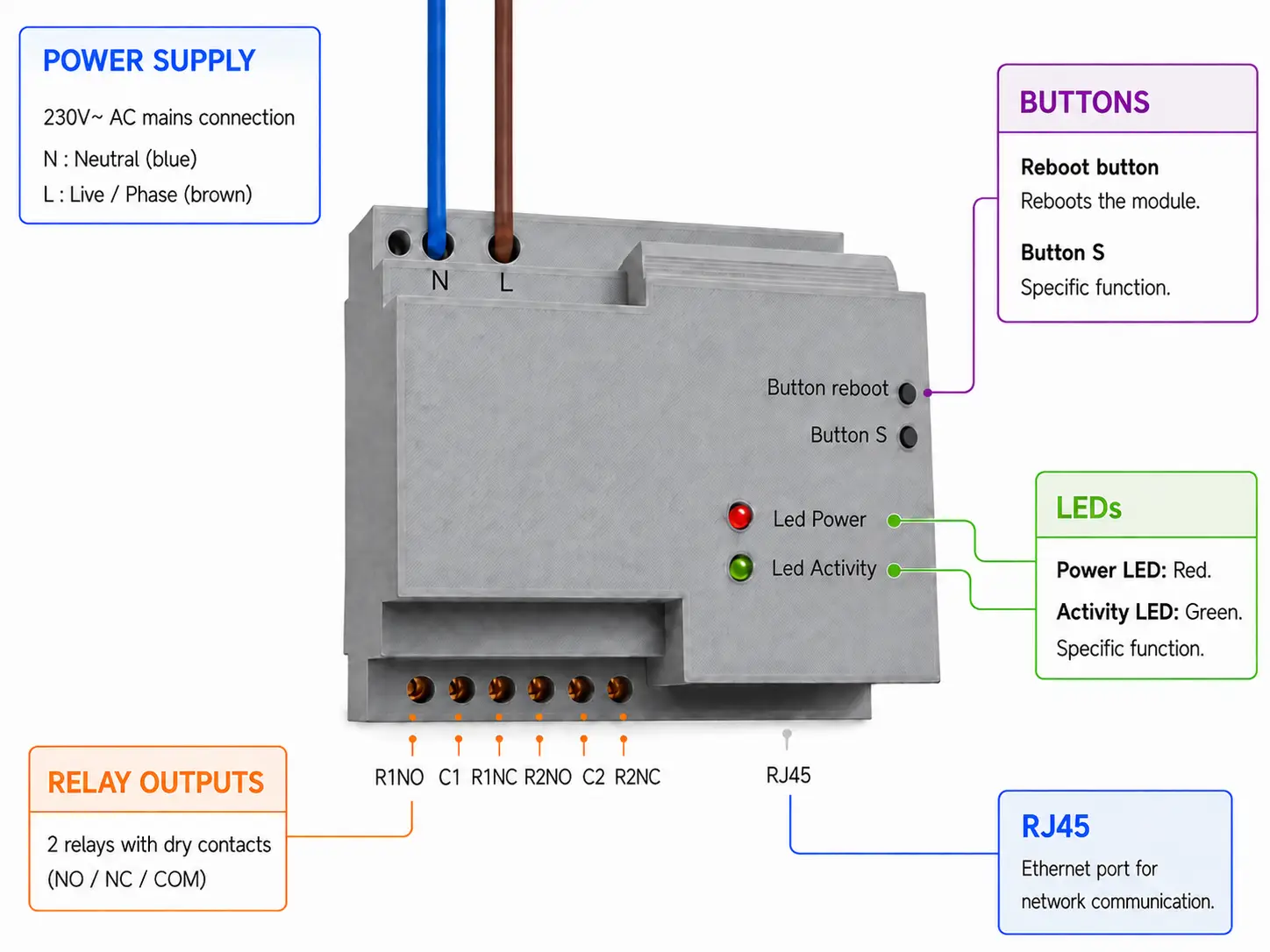
Relay box hardware diagram
Using the diagram below, you can identify the power connection, relay outputs, RJ45 connector, buttons, and status LEDs.
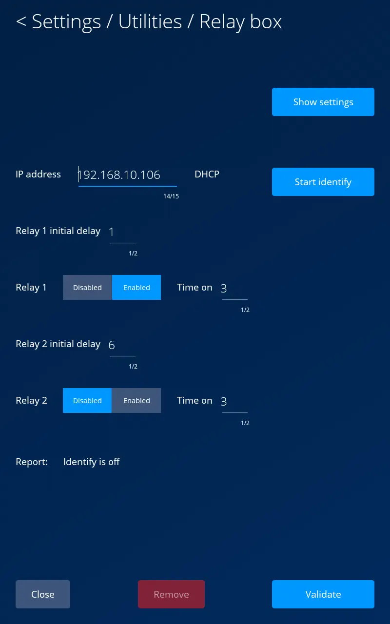
The relay box initially uses DHCP. Before configuring its relays, you must change its IP address. After entering a new address, the relay box switches to a static IP configuration. A static address is required for reliable operation.
Important: Configure the relay box IP address before adjusting the relay sequence.
Enable or disable each relay as required, then configure the opening sequence by specifying the initial delay and activation time for Relay 1 and Relay 2. Select “Verify” to save the configuration.
Reset via the intercom
On the relay box settings page, select “Remove” to unpair it and reset the relay box to its default configuration.
Manual reset on the relay box
If the S button is held down for too long, the activity LED stops flashing and stays on continuously. In this case, the reset process is cancelled and must be started again.